Lorentz Aerospace
FIELD-MEDIATED FLIGHT & PLASMA ENVELOPE VEHICLES
LORENTZ AEROSPACE
Every aircraft ever built negotiates with the air. Wings deflect it. Jets compress and expel it. Rockets carry their own reaction mass and throw it backward. All are constrained by the same physics: friction at the boundary, thermal loading at the surface, and the energetic cost of pushing through a medium that pushes back.
Lorentz Aerospace investigates a vehicle that does not negotiate with the medium. It replaces the medium. A self-sustaining envelope of magnetized plasma surrounds the hull. Inside the bubble, the vehicle sits in near-vacuum. No air touches the hull. No boundary layer forms. No shock wave propagates. The craft is aerodynamically invisible — the plasma envelope interacts with the atmosphere on the craft’s behalf.
We do not push harder through the atmosphere. We reshape the interface. The plasma envelope is the discipline.
01 — The Discipline
Lorentz Aerospace exists to collapse five constraints simultaneously: aerodynamic drag, boundary-layer thermal loading, control-surface response lag, propulsion energy density, and the atmospheric interface limit on sustained high-Mach flight. Every conventional aircraft accepts these constraints and engineers tradeoffs against them: a faster aircraft requires a hotter skin, more fuel, and more refined control. The five limits compound; pushing one harder makes the others worse.1
Field-mediated flight breaks the compounding by changing what the hull touches. If the hull is wrapped in a controlled magnetized plasma envelope, the boundary between the craft and the outside atmosphere moves outward by tens of centimetres. The plasma carries the aerodynamic load; the hull carries no friction, no shock, no convective heating. Drag becomes a function of the envelope’s geometry and conductivity, not the hull’s. Thermal loading becomes a function of the plasma’s residence time at the boundary, not the hull’s material limits. Control becomes a function of how the envelope is shaped, not how a flap is moved.2
The discipline of Lorentz Aerospace is the engineering of that envelope at vehicle scale. Plasma generation. Field confinement against magnetohydrodynamic instabilities. Real-time envelope shaping. Power generation matched to the envelope’s sustained energy budget. Vehicle classes spanning low-Mach atmospheric demonstrators through hypersonic boundary-layer management to speculative full-envelope vehicles.
02 — The Bottleneck
Conventional subsonic flight is limited by lift-to-drag ratio and engine bypass efficiency. Both numbers have improved incrementally for sixty years and are within ten percent of their thermodynamic limits. There is no Moore’s Law for the wing; doubling fuel efficiency on a long-haul jet requires either a wholly new airframe or a wholly new propulsion architecture, and neither has emerged.3
Supersonic and hypersonic flight is limited by the boundary layer. At Mach 5 the stagnation temperature of air against a vehicle’s leading edge exceeds two thousand degrees Celsius — hot enough to ablate metals and oxidize ceramics. The only mature engineering response is to throw exotic materials at the problem (carbon-carbon composites, ultra-high-temperature ceramics, transpiration cooling) and to accept that the hull is consumable. Reusable hypersonic vehicles remain a research target after sixty years of attempts.4
Plasma actuator research over the last two decades has demonstrated that even small amounts of localised plasma at the right surface location can dramatically alter boundary-layer behaviour: delay separation, reduce skin friction, suppress shock formation. The energy cost of those localised actuators is small fractions of the aerodynamic energy they save. The next step — a continuous envelope rather than discrete actuators — is the engineering hop Lorentz Aerospace exists to make.5
The shared bottleneck across all five constraints is the hull-medium interface. Conventional aerospace cannot move the interface away from the hull because the hull IS the interface. Field-mediated flight separates them: hull on the inside, plasma envelope on the outside, vacuum between. Every conventional limit is now a function of the envelope, not the hull.
03 — The Plasma Envelope
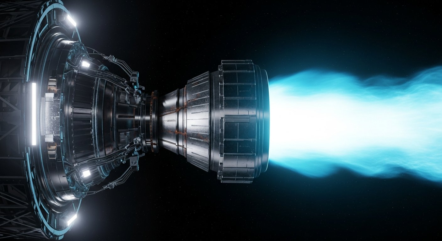
The flagship research target is the XR-1: a manned-scale demonstrator surrounded by a self-sustaining envelope of magnetized plasma. The envelope is generated by hull-mounted superconducting coils that produce a magnetic field strong enough to ionize the surrounding atmosphere into a confined plasma layer. The plasma is held in a closed magnetic geometry that the craft carries with it; aerodynamic interaction happens between the plasma and the outside air, not between the air and the craft.6
This is not an anti-gravity claim. It is not propellantless propulsion. The plasma envelope is a control surface and a thermal-management substrate; thrust still comes from conventional channels (Lorentz force on induced currents in the surrounding air for atmospheric flight, or seeded-plasma magnetic-nozzle ejection for vacuum). The envelope is what makes high-speed atmospheric flight thermally sustainable; the propulsion is a separate stack.
The envelope geometry is dynamically reshaped at microsecond cadence to manage shock formation, drag distribution, and lift. A trailing low-energy region produces thrust by pulling the surrounding ionized atmosphere through the asymmetric field, transferring momentum to the craft. A high-pressure leading region streamlines the shock around the vehicle so no compression heating reaches the hull. The vehicle steers by adjusting the field geometry, not by deflecting a control surface.7
The physics that makes this possible has been established since the mid-twentieth century: magnetohydrodynamics, soliton dynamics, ponderomotive forces, Debye sheath theory. Nothing in the envelope concept depends on exotic physics. The gap from existing physics to a flying demonstrator is engineering: high-current superconducting coils, real-time MHD simulation, control loops that anticipate plasma instabilities before they grow, and the integration of all three into a vehicle-scale platform.
04 — MHD Control and Field Steering
The plasma envelope is a high-beta magnetohydrodynamic equilibrium that wants to collapse. Kink instabilities grow on ten-microsecond timescales; ballooning modes on the order of two microseconds. A vehicle built in the 1980s with the same physics could form the envelope but could not keep it alive long enough to be useful; the technology to predict and counteract MHD instabilities in real time did not exist. That window opened in the 2010s with the convergence of three enabling capabilities: FPGA-based microsecond-cadence signal processing, lattice-Boltzmann MHD simulation that runs faster than the plasma evolves, and neural surrogate models that predict instability onset from sensor data.8
The control loop runs at one megahertz across a distributed sensor mesh on the inside of the hull. Each sensor reports local field strength, ion density, and electron temperature; the central solver fuses these into a three-dimensional envelope state estimate; an inverse-control module computes the per-coil current adjustments that drive the envelope toward the commanded geometry. Total sensor-to-actuator latency is approximately five microseconds — ten times faster than the fastest documented MHD instability growth rate.
Lorentz force on the surrounding air is the primary thrust mechanism in atmospheric flight: the field’s interaction with induced currents in the ionized boundary outside the envelope transfers momentum. In a vacuum or near-vacuum environment, a seeded-plasma magnetic nozzle replaces this mechanism — cesium-vapor injection at the envelope boundary forms a tail of magnetized plasma that the same field geometry directs aft, producing thrust by mass ejection. The two regimes share the same hull, the same coils, and the same control loop; what changes is the plasma source.9
The field design is supplied by neighbour-discipline magnet engineering. The XR-1 carries roughly 1,440 high-temperature superconducting coil segments distributed across the hull surface, producing local field strengths above twenty tesla at twenty kelvin operating temperature. The coil design and the cryogenic support are jointly developed with Highfield Magnetics; the field-modelling solver is co-developed with Maxwell Continuum.
05 — Power, Heat, and Materials
The XR-1 envelope requires a sustained power supply on the order of forty megawatts to maintain ionization and to drive the field-shaping currents. Conventional turbine power generation cannot match this density at vehicle scale; battery storage cannot match the duration. The XR-1 program depends on compact fusion power from Stellar Furnace’s SF-1 dense plasma focus reactor, which produces forty megawatts net electrical in an eight-metre form factor with direct alpha-particle-to-electricity conversion at 65 to 75 percent efficiency.10
Heat rejection is a parallel constraint. Even with a plasma envelope intercepting the bulk aerodynamic heating, the hull must reject roughly eighteen kilowatts of cryogenic load (the coil cooling) plus several hundred kilowatts of control electronics waste heat. The thermal architecture uses superfluid helium loops developed with Phase Flash’s cryogenic platform line, distributed across the hull as a network of capillary-machined channels.
The hull material stack must survive the cryogenic interior, the room-temperature plenum, and the plasma-facing exterior simultaneously. The outer skin is a triazite tungsten-rhenium-hafnium-carbide alloy supplied by Metallic Sciences; the structural fibre is carbon-nanotube composite for tensile strength at one-third the mass of aluminium; the inner insulation is engineered polymer composite from Polymer Press producing thermal isolation between the cryogenic and the warm interior volumes.11
The coil geometry is fabricated by precision machining of the polymer-V mandrels (supplied by Polymer Press) and assembled by robotic micro-positioning at five-micrometre tolerance using Foundation Kinetics’s Scarab class of compact actuators. The complete vehicle assembly is one of the most cross-discipline integrated programs in the network.
06 — Vehicle Classes
The program develops in six vehicle classes spanning a fifteen-year roadmap from atmospheric demonstrators to speculative full-envelope vehicles. The classes are ordered by maturity of the underlying physics and the engineering risk of each step.
Each class is intended to validate one or two specific engineering hooks before the next class begins. Class A demonstrates that plasma-based aerodynamic control scales beyond the lab. Class B demonstrates that a partial envelope reduces thermal load enough to escape ablative-TPS dependence. Class C demonstrates that a closed envelope can be sustained on a small vehicle. Class D demonstrates manned-scale envelope flight with compact fusion power. Class E and Class F are extrapolations from Class D, dependent on its success.
07 — Supplier Integration
The XR-1 program integrates technology from across the engineering network. The supplier-and-integration stack is the engineering of the upstream and adjacent components that make each vehicle class possible.
Stellar Furnace — SF-1 dense plasma focus reactor: forty megawatts net electrical output in an eight-metre form factor. Direct alpha-to-electricity conversion at 65 to 75 percent efficiency. Without compact fusion the XR-1 is a ground-tethered capacitor-bank demonstrator at best.
Highfield Magnetics — 1,440 REBCO superconducting coil segments. Iron Horse twenty-tesla solenoid technology productized at vehicle scale. The God Magnet pulsed array variant for magnetic-nozzle propulsion in the vacuum-regime variant.
Metallic Sciences — Triazite tungsten-rhenium-hafnium-carbide outer skin. Carbon-nanotube structural fibre. Refractory leading-edge tile inventory for the Class B hypersonic boundary-layer demonstrator.
Polymer Press — Polymer-V mandrels for coil winding. Engineered polymer thermal insulation between cryogenic and warm-interior volumes. Substrate engineering for vehicle skin underlays.
Phase Flash — Cryogenic platform line extended into hull-distributed superfluid helium loop. The same vacuum-and-cryogenic engineering that ships the desalination Oasis ships the XR-1 cryogenic plant.
Maxwell Continuum — Field-modelling solver and electromagnetic continuum simulation. The 60 GHz gyrotron diagnostic suite for in-flight envelope state estimation. Communications and radar sensing modules that operate above the plasma cutoff frequency.
Aetheric Sciences — Monolith flight-management processor at three nanometre process node. Real-time control of the MHD envelope: distributed-sensor fusion, instability-prediction neural surrogate, per-coil current adjustment. Autonomous flight operations for the Class A and Class C vehicles.
Vapor Vacuum — Ground test facility vacuum-chamber engineering for the Class C and Class D static-envelope characterization tests. Bismuth-magnesium metamaterial deposition at sub-nanopascal pressure for plasma-facing-component lifetime testing.
Foundation Kinetics — Arachne-7 weaver for hull assembly at vehicle scale. Scarab class compact actuators for coil-winding micro-positioning at five-micrometre tolerance. Robotic test rigs for static envelope characterization.
Fermat Logistics — XR-VAC vehicle ferry operations once Class E reaches operational tempo. Terminal infrastructure for hypersonic transport in Class F. Commercial deployment operations across the network.
Stellar Furnace → Highfield Magnetics → Metallic Sciences → Polymer Press → Phase Flash → Maxwell Continuum → Aetheric Sciences → Vapor Vacuum → Foundation Kinetics → Fermat Logistics →
08 — Validation Hooks
The forward research program names six measurable claims. Each is intended to be a future Crystal Ball-grade prediction registration once the prediction infrastructure exists. The hooks structure the surface where external scientific progress feeds the program roadmap.
HOOK A — plasma actuator drag reduction at flight scale. Laboratory plasma actuators have demonstrated 5 to 15 percent skin-friction reduction in wind-tunnel conditions. Translation to flight-scale UAVs is the Class A gating measurement. Sustained 10 percent L/D improvement at a representative subsonic operating point would close Hook A.12
HOOK B — sustained hypersonic boundary-layer management without ablative TPS. Today’s hypersonic vehicles consume their leading edges over the duration of the flight. A partial plasma envelope that intercepts the stagnation flow before it reaches the hull material would relax the ablative constraint. A one-thousand-second sustained burn at Mach 5 in atmospheric flight without ablative material consumption is the Class B closing measurement.
HOOK C — MHD instability prediction at vehicle scale. Current MHD stability is demonstrated in laboratory plasma experiments at microsecond cadence. Translation to a closed envelope on a vehicle-scale platform, with instabilities suppressed before they grow to disruptive amplitude, is the central Class C closing measurement.13
HOOK D — compact fusion power density at vehicle scale. The SF-1 program’s success is a prerequisite for Class D. Forty megawatts of net electrical from a hull-mounted reactor is the gating measurement; the vehicle program cannot proceed without it.
HOOK E — sustained-flight envelope cost per controlled flow volume. The energy cost of maintaining the envelope (ionization plus field-shaping) per cubic metre of controlled atmospheric flow is the operational economics metric. Reducing this cost below a target threshold makes the envelope economically competitive with conventional aerodynamics on commercial routes.
HOOK F — full-envelope vehicle thermal flux at sustained hypersonic. The longer-term research target: sustained Mach 8-plus atmospheric flight with hull thermal flux below the limits of conventional structural alloys. Demonstration on the Class F transport vehicle is the gating measurement for commercial hypersonic transport.14
Edison observability of arXiv claims in plasma aerodynamics, MHD flow control, hypersonic boundary-layer management, compact fusion power, pulsed-power miniaturization, and high-temperature superconductors would feed forward into roadmap revision. The integration is left as a future build and is not implemented in this sprint.
RESEARCH REPOSITORY
Plasma aerodynamics, MHD flow control, hypersonics, pulsed power, materials, thermal protection, and high-cadence control systems.
Lorentz Aerospace is the engineering of field-mediated flight: replacing the hull-medium interface with a controllable plasma envelope. The discipline collapses five conventional aerospace constraints (drag, thermal loading, control lag, propulsion density, atmospheric interface limit) into one engineering variable — the envelope’s field geometry. The forward roadmap spans atmospheric plasma-actuator demonstrators through speculative full-envelope hypersonic transport, each class gated on the validation hooks of the previous.
(wiki) Plasma Actuator • (wiki) Dielectric Barrier Discharge • (wiki) Boundary Layer • (wiki) Active Flow Control
Reference Links — MHD & Field Control(wiki) Magnetohydrodynamics • (wiki) Lorentz Force • (wiki) Debye Sheath • (wiki) MPD Thruster
Reference Links — Hypersonics(wiki) Hypersonic Speed • (wiki) Scramjet • (wiki) Atmospheric Entry • (wiki) Ablative Heat Shield
Reference Links — Pulsed Power & Materials(wiki) Pulsed Power • (wiki) Superconducting Magnet • (wiki) UHTC • (wiki) Carbon Nanotube Composites
- Anderson, J.D. Hypersonic and High-Temperature Gas Dynamics. 3rd Ed. AIAA, 2019. ISBN 978-1-624-10514-2. Reference for hypersonic boundary-layer physics.
- Goldston, R.J. & Rutherford, P.H. Introduction to Plasma Physics. CRC Press, 1995. ISBN 978-0-7503-0183-1. Reference for plasma kinetic theory.
- Davidson, P.A. An Introduction to Magnetohydrodynamics. 2nd Ed. Cambridge Univ. Press, 2017. ISBN 978-1-107-16016-3.
- Sutton, G.P. & Biblarz, O. Rocket Propulsion Elements. 9th Ed. Wiley, 2017. ISBN 978-1-118-75388-0.
- Roth, J.R. Industrial Plasma Engineering Volume 2: Applications to Nonthermal Plasma Processing. CRC Press, 2001. ISBN 978-0-7503-0545-7.
- Corke, T.C. et al. "Dielectric barrier discharge plasma actuators for flow control." Annu. Rev. Fluid Mech. 42, 505–529 (2010).
- Moreau, E. "Airflow control by non-thermal plasma actuators." J. Phys. D: Appl. Phys. 40, 605–636 (2007).
- Leonov, S.B. & Yarantsev, D.A. "Plasma-induced aerodynamic effects in a high-speed flow." Plasma Sources Sci. Technol. 16, 132–138 (2007).
- Sheikin, E.G. & Bityurin, V.A. "Hypersonic MHD flow control: a review." AIAA Paper 2005-3478, 2005.
- Macheret, S.O. et al. "MHD energy bypass scramjet engine with onboard magnetic field generation." AIAA Paper 2004-1191, 2004.
- Bityurin, V.A. et al. "Theoretical investigation of MHD interaction in supersonic flow." AIAA Paper 2003-0173, 2003.
- Sorbom, B.N. et al. "ARC: A compact, high-field, fusion nuclear science facility and demonstration power plant with demountable magnets." Fusion Eng. Des. 100, 378–405 (2015).
- Whyte, D.G. et al. "Smaller & sooner: exploiting high magnetic fields from new superconductors for a more attractive fusion energy development path." Journal of Fusion Energy 35, 41–53 (2016).
- Reinovsky, R.E. et al. "Magnetic flux compression generator overview." Proc. 14th IEEE Pulsed Power Conference, 2003.
- ● Conventional aerospace constraint compounding: standard aerodynamics. The drag-thermal-control tradeoff is the basis of every airframe design tradition.
- ● Plasma envelope as aerodynamic-load-bearing surface: theoretical extrapolation from boundary-layer plasma actuator work. Vehicle-scale demonstration is the engineering hop.
- ● Subsonic flight near thermodynamic limit: standard engine and airframe efficiency data; incremental improvements are well-bounded.
- ● Hypersonic boundary-layer thermal limit: standard hypersonics. Mach 5 stagnation temperatures exceed 2000°C; ablative material consumption is the documented engineering response.
- ● Plasma actuator scaling: demonstrated in wind-tunnel; scaling to full flight is engineering work in progress at multiple research labs.
- ● XR-1 closed plasma envelope: engineering program target, not yet demonstrated at vehicle scale. Constituent technologies (HTS coils, MHD control, compact fusion) are individually mature.
- ● Envelope thrust mechanism: theoretical, based on Lorentz-force coupling to induced currents in surrounding ionized atmosphere. Mass-thrust calculations are standard MHD; sustained operation is the engineering hop.
- ● MHD instability suppression at microsecond cadence: lab-demonstrated in fusion plasma confinement. Vehicle-scale translation is the engineering gap.
- ● Magnetic-nozzle vacuum propulsion: engineering program. Cesium-seed mass-injection magnetic-nozzle thrusters are operational at small scale; vehicle integration is the open work.
- ● Compact fusion power dependency: the XR-1 program is gated on Stellar Furnace SF-1 success. Without compact net-positive fusion in an eight-metre form factor, the XR-1 cannot fly autonomously.
- ● Triazite W-Re-HfC alloy + CNT composite material stack: developed by Metallic Sciences; documented thermal and tensile properties; integration into vehicle-scale hull is the engineering scope.
- ● Plasma actuator drag reduction: 5–15% laboratory demonstration; flight-scale translation is the Class A engineering target.
- ● MHD instability prediction at vehicle scale: theoretical extrapolation from fusion-confinement experiments. Five-microsecond control latency is the design target; full-system demonstration is the gating measurement.
- ● Full-envelope sustained Mach 8 transport: long-term speculative target. Depends on Classes A–E all reaching their respective closing measurements. Commercial deployment is decades out.