POWER
- Turboshaft engines
- Generators
- HVDC bus
- High-frequency conversion
- Pulse power where the discharge needs it

Magnetohydrodynamic propulsion
XR-1 is a preliminary design for a turboelectric aircraft that transfers momentum to ambient air through a distributed electromagnetic actuator.
RF excitation creates a controlled conductive region in the surrounding atmosphere. High-field magnetic hardware drives and shapes current through that region. Collisions transfer electromagnetic force into the neutral gas, producing a directed atmospheric momentum flux.
Program status — analytical design and ground-test architecture
02
The question
Can a compact electromagnetic atmospheric actuator transfer enough electrical power into directed neutral-air momentum to support useful flight?
A helicopter answers that question with blades. It throws air downward, and the air throws the helicopter up. XR-1 asks whether the same job can be done with fields instead of blades: no rotor, no propeller, no exhaust, and the air around the aircraft as the working fluid.
The atmosphere is the reaction mass.
Nothing in the idea escapes Newton. To stay up, a 10-tonne aircraft must push about 98 kilonewtons of air downward, every second it hovers. The only question is what does the pushing. Here the chain is long, and every link in it is ordinary physics:
The chain is sound. Whether it is efficient enough to fly is the open question, and it is the only one this program exists to answer.
03
The force
The magnetic field does not push ordinary air directly. Lorentz first creates mobile charge carriers in a controlled region of the atmosphere. Electric current flowing through that region interacts with the magnetic field. The resulting Lorentz force acts on charged particles, which transfer momentum through collisions to the much larger neutral population.
The objective is not to accelerate a tiny plasma jet. The objective is to turn a large volume of surrounding atmosphere into the effective working fluid of a distributed actuator.
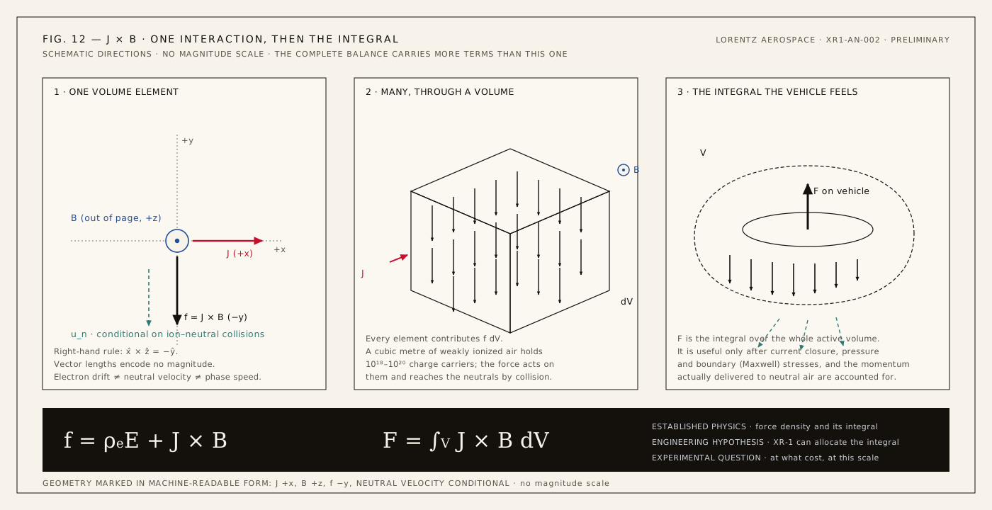
Summed over a volume, the force density becomes a force the vehicle can feel:
XR-1 is an attempt to engineer that integral.
The integral is only the start of the accounting. Useful vehicle force depends on where the current closes, on pressure stresses, on boundary terms and above all on how much of the momentum actually reaches neutral gas. The currents and magnets are carried by the vehicle, so internal forces between them cancel; a force that stays inside the machine lifts nothing. Thrust exists only as momentum delivered to external atmospheric mass. Established physics
Electric fields alone can move air. Ionic wind, or electrohydrodynamic thrust, is real atmospheric momentum transfer: ions dragged through the air by an electric field collide with neutrals and set them moving. It has flown a small solid-state aeroplane. Lorentz investigates a different route, current crossing a magnetic field, and asks whether magnetic coupling opens a substantially different regime of body-force and thrust density. Any measurement must separate the two. Established physics Experimental question
04
The working fluid
The atmosphere is both propellant and problem.
Air at sea level is an excellent insulator. That is why lightning is rare and power lines work. Before any magnetic force can act, the machine must first make the air electrically accessible.
Very little ionization is needed to make air conduct. At the reference density used on this page, one molecule in about twenty-five million carries a charge. The charged particles collide with neutral molecules about a trillion times per second. Those two facts decide almost everything downstream. The collisions pass forces from the charged minority to the neutral majority within nanoseconds, which is what makes momentum transfer possible at all. The same collisions turn electrical energy into heat, which is what makes it expensive. Established physics
And the conductivity does not last. A free electron in sea-level air is captured by an oxygen molecule within nanoseconds to tens of nanoseconds, depending on how hot it is. Conductivity is a perishable good: it must be made continuously, and paid for continuously.
The candidate mechanism is millimetre-wave electron heating. Microwave fields energize the few free electrons already present; energetic electrons knock further electrons loose by impact; the ionization must be sustained against attachment, recombination and transport. The useful ionization fraction is an experimental result, not a design percentage. Established physics for the mechanism; Experimental question for the yield.
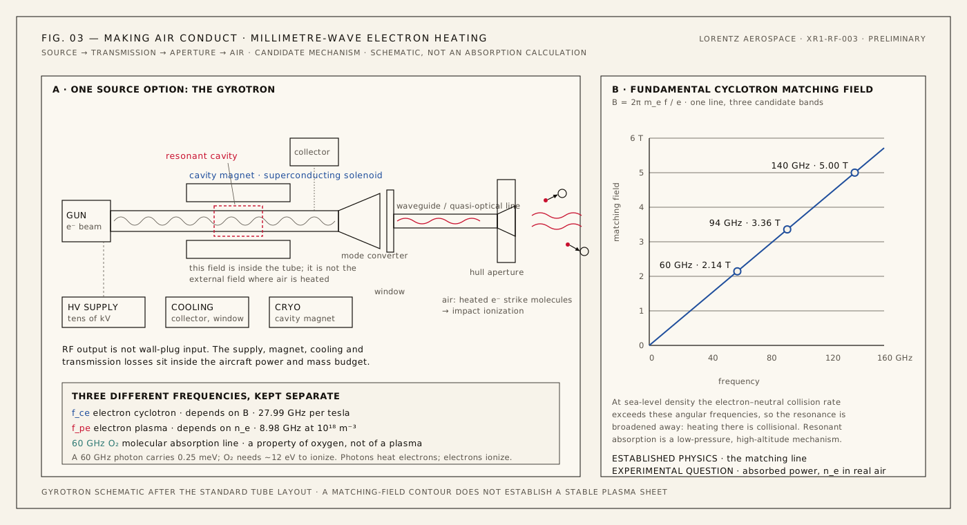
A gyrotron converts energy from a gyrating electron beam into millimetre-wave radiation inside a magnetic cavity. Megawatt-class tubes exist: ITER's 170 GHz gyrotrons have delivered 1 MW for 1000 s, and Wendelstein 7-X heats its plasma with ten 140 GHz gyrotrons of nearly 1 MW each. Those are fusion-laboratory installations with their own halls, supplies and cryoplants. Packaging one for an aircraft is a design problem, not a physics one. Its high-voltage supply, launcher, transmission and cooling belong in the power and mass budgets, and its cavity magnet is distinct from the external magnetic field where the atmospheric plasma would interact with the beam. Established physics for the source; Design target for carrying it.
A 60 GHz photon carries 0.00024814 eV; oxygen's ionization energy is about 12.07 eV in the NIST Chemistry WebBook. A microwave photon cannot directly ionize an oxygen molecule. The route is electron heating followed by impact ionization, not photoionization. Established physics
05
The complete machine
A conventional aircraft moves air with surfaces. XR-1 moves air with a volume.
XR-1 is a ten-metre, ten-tonne research configuration built around one idea: an annular electromagnetic actuator on its underside, divided into thirty-two independently driven sectors. Every drawing on this site uses the same vehicle, the same annulus and the same sector numbering. Design target
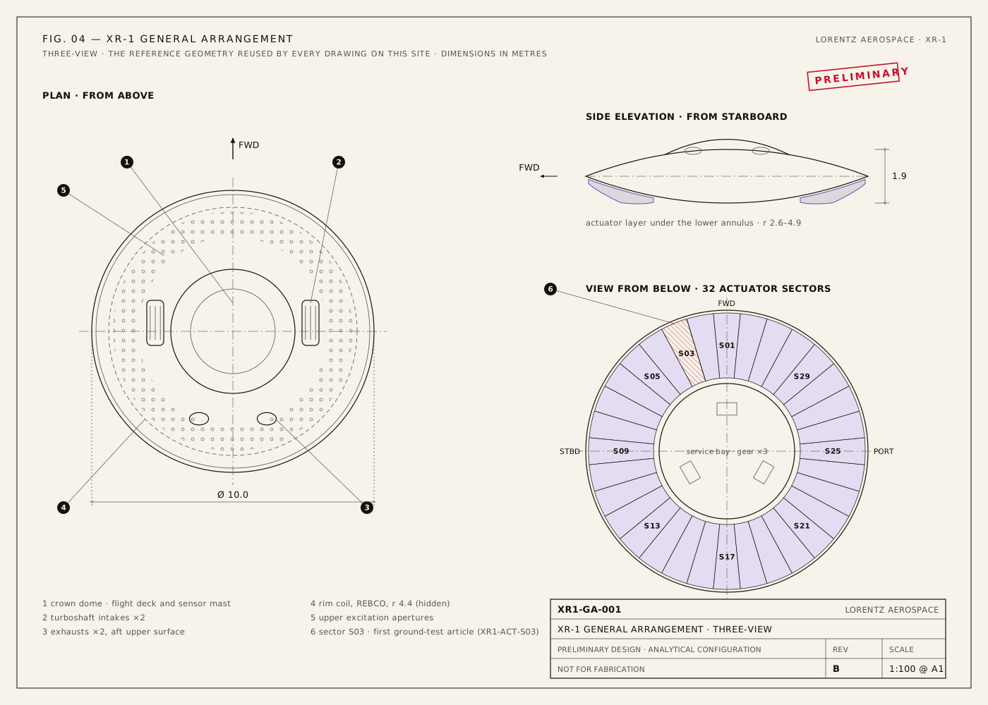
The shape follows the fields. A flattened disc gives a long circumference for actuator area, radial symmetry for distributed control, a natural home for a large ring coil, short structural paths and a big internal volume. It is a candidate, not a uniquely correct solution: linear segments, partial annuli and other open-flow geometries stay in the comparison. The geometry study covers roughly 7.5–10 m and 10–12 tonnes, with hover-scale reaction thrust of 100–120 kN. Design target
The aircraft is inside the engine.
A helicopter's rotor is a fixed object. XR-1's rotor would be a region of air: wherever the excitation makes it conductive, wherever current flows through it, wherever the field crosses it. At the level of momentum theory, the actuator performs the same job as a rotor: it accelerates atmospheric mass downward. The difference is that a distributed electromagnetic body force replaces mechanical blades, and its shape can be changed in milliseconds.
Six subsystem groups. Each one is recognizable engineering; the program's risk lies in how they couple. Design target
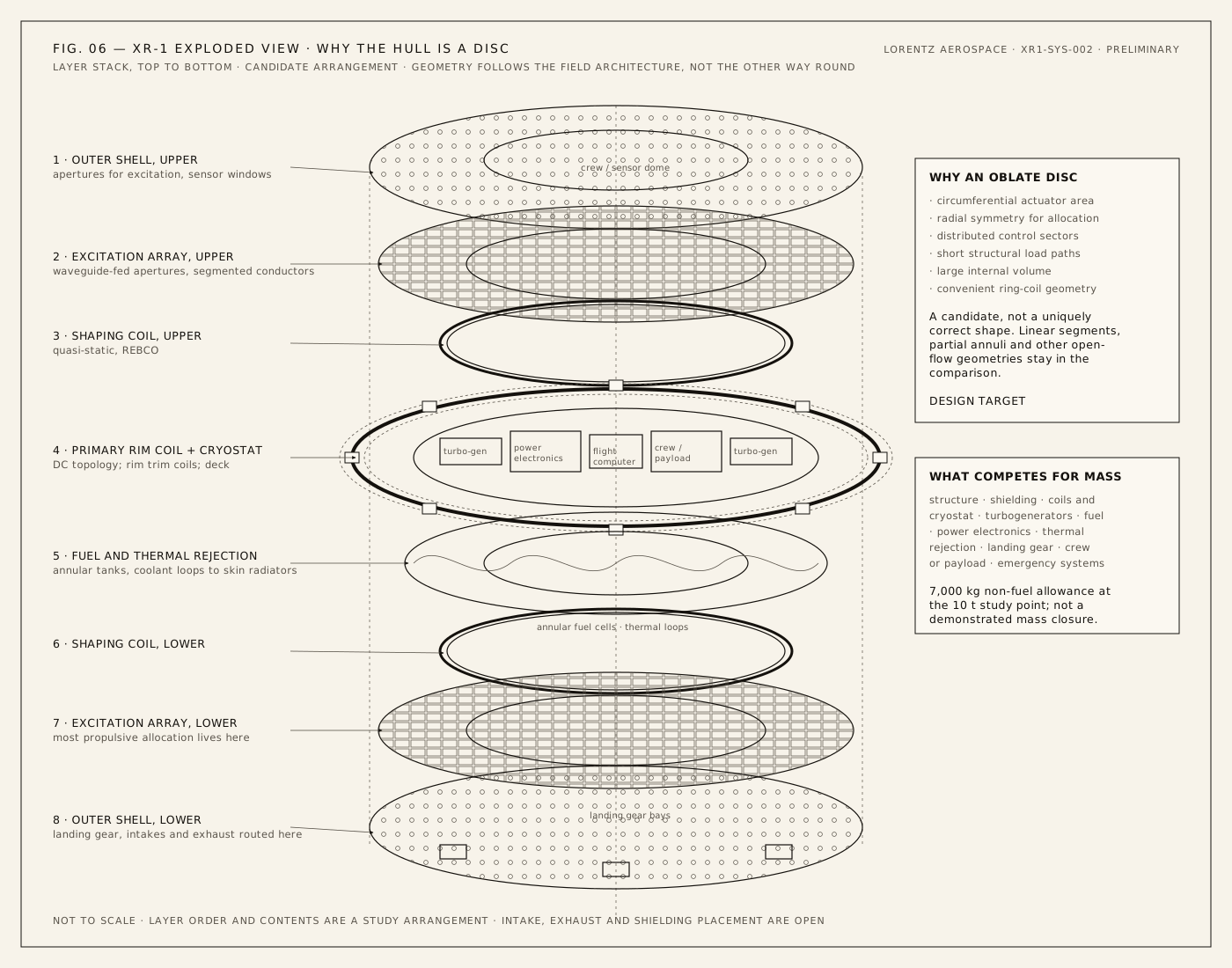
Propulsive airflow beneath the hull is distinct from any aerodynamic boundary-layer or shock effect; the two cannot be counted twice as thrust, and no elimination of sonic booms is assumed. Structure, shielding, intakes, landing hardware, fuel, thermal rejection and emergency behaviour all compete for the same mass budget.
06
Momentum
EngineeringMoving enough air to hover is not inherently the impossible part. Efficiently coupling electromagnetic power into that air may be.
How to read the numbers
Nothing on this page has flown. From here on every claim carries one of six labels, so a reader always knows which kind of statement it is. The Lorentz force is textbook physics; the aircraft built around it is a hypothesis with a staged experimental program in front of it.
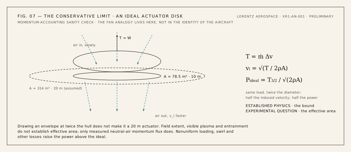
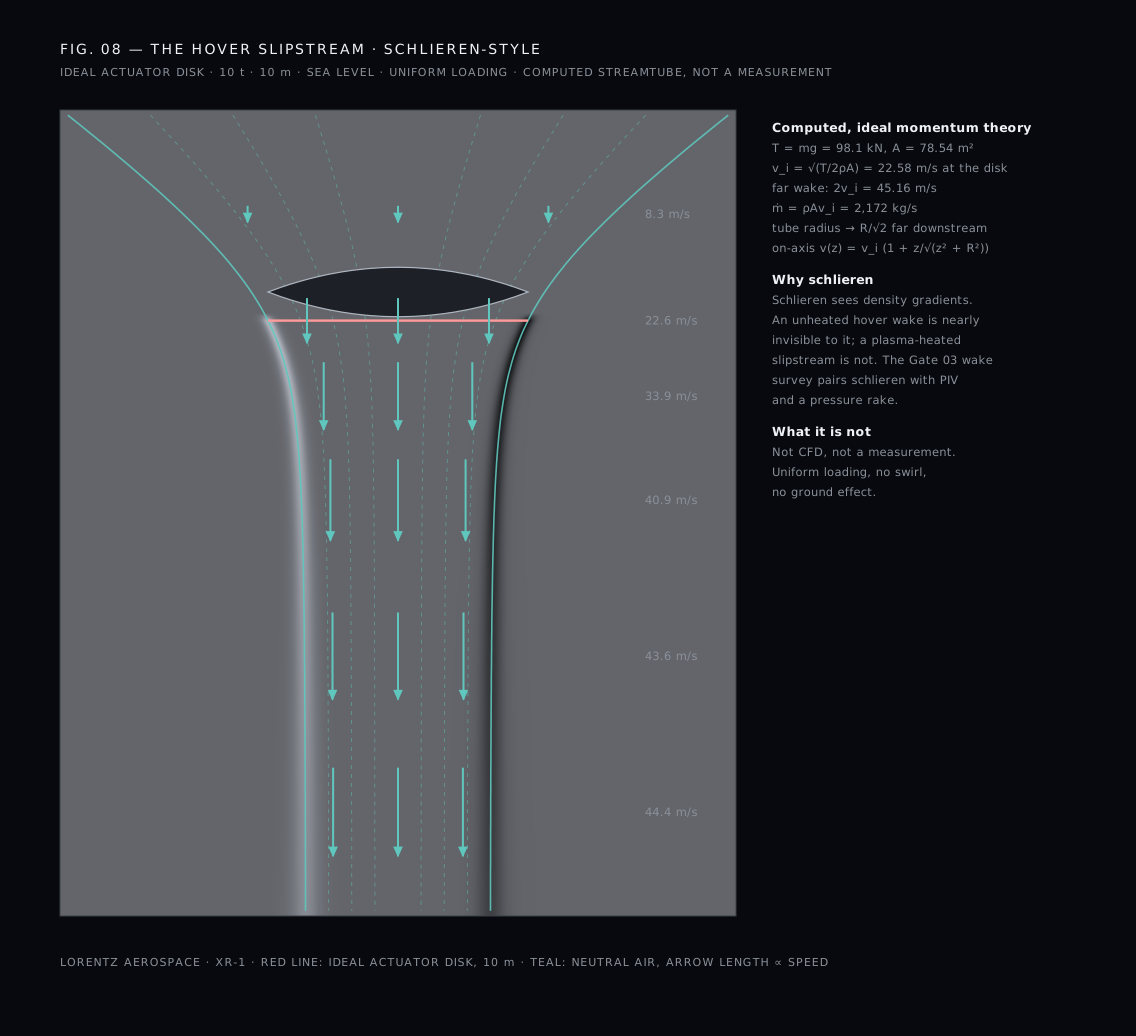
Start with what any hovering machine must do, whatever it is made of. Actuator-disk theory, the momentum balance behind every helicopter rotor, gives the minimum power needed to hold a weight up by pushing air through a disk of a given area. It does not care whether the disk is made of blades or of fields. It follows NASA Glenn's actuator-disk explanation; use $\rho=1.225\,\mathrm{kg/m^3}$ and $g=9.81\,\mathrm{m/s^2}$, sea level, out of ground effect. Established physics
| Quantity | 10 m effective diameter | 20 m effective diameter |
|---|---|---|
| Area | 78.54 m² | 314.16 m² |
| Hover thrust | 98.10 kN | Same load |
| Induced velocity at the disk | 22.58 m/s | 11.29 m/s |
| Air mass flow | 2,172 kg/s | twice the area, half the velocity |
| Far-wake velocity, 2vi | 45.16 m/s | 22.58 m/s |
| Ideal airflow power | 2.215 MW | 1.1075 MW |
| Electrical input at 25% all-in efficiency | 8.860 MW | 4.430 MW |
| Electrical input at 15% all-in efficiency | 14.767 MW | 7.383 MW |
About 2.2 MW of ideal air power. A 10 MW electrical study architecture.
That is the benchmark. A perfect actuator of 10 m effective diameter needs 2.2 MW delivered to the air to hold 10 tonnes; the XR-1 study carries 10 MW of electrical input. So the architecture closes on paper only if at least 22.15% of all electrical input ends up as directed kinetic power in the neutral air. A good helicopter rotor turns most of its shaft power into that kind of flow. The central challenge is plain: can a distributed electromagnetic actuator approach useful fractions of conventional momentum-transfer efficiency? Ten megawatts does not prove feasibility. It sets the target. Design target Experimental question
One reconciliation belongs here. The 10 m diameter is the hull; the physical actuator annulus (2.6 to 4.9 m radius) covers 54.19 m², not 78.54 m². If only the annulus carried momentum, the ideal power would rise to 2.667 MW. Whether the induced flow fills the whole disk, or reaches beyond the hull as the envelope concept hopes, is a measurement. A 10 m hull has not been shown to actuate a 20 m disk. Field extent, visible plasma and entrainment do not establish effective area; only the measured neutral-air momentum flux does. The table assumes ideal flow; nonuniform loading, swirl and other losses raise the requirement. Experimental question
07
Where the power goes
EngineeringThe field equation is easy. The power budget is not.
Ten megawatts go in. Some fraction comes out as air moving downward. Everything else becomes heat, light or motion that lifts nothing. The program is, at bottom, a hunt for that fraction.
Two costs attach to any steady interaction volume, and they pull in opposite directions. Established physics
The first is Ohmic. For a fixed force $F$ carried uniformly by a volume $V$ in a field $B$, dissipation falls with conductivity, with the square of the field, and with volume. The second is the cost of keeping the gas conducting at all: every free electron in sea-level air is soon lost, mostly by attachment to oxygen, and each replacement costs at least the energy per ion pair, about 34 eV in air (NPL summary of the recommended W-value). That cost grows with volume. Between them sit the three knobs the design actually has: how large the active volume is, how dense the ionization is, and how strong the field is.
| Quantity | Inputs | Value |
|---|---|---|
| Scalar conductivity $\sigma=n_ee^2/m_e\nu_{en}$ | $n_e=10^{18}\,\mathrm{m^{-3}}$, assumed $\nu_{en}=2\times10^{12}\,\mathrm{s^{-1}}$ | 0.0141 S/m |
| Ohmic power for the reference load | $F=98.1$ kN, $B=5$ T, $V=50\,\mathrm{m^3}$, $\sigma=1$ S/m | 7.70 MW; ten times more at 0.1 S/m |
| Sustaining power density | $n_e=10^{18}\,\mathrm{m^{-3}}$, assumed $\nu_{\mathrm{loss}}=10^{7}\,\mathrm{s^{-1}}$, $W_i=34$ eV | 54.5 MW/m³ |
Read those rows together. With textbook-order inputs, a steady, uniform, sea-level, 50 m³ interaction volume does not close on 10 MW; it misses by more than an order of magnitude on each cost. That is not a verdict on the concept. It is the specification of the first experimental gate: which combination of pulsed rather than continuous excitation, altitude (three-body attachment scales with the square of gas density, so it falls faster than the air thins), electron temperature (hot electrons attach less readily and detach more), field strength (Ohmic cost falls as $1/B^2$; a REBCO magnet has held 20 T) and geometry (thin, strongly driven regions rather than a uniform volume) brings the two costs down together. The Princeton group's argument that the energy cost of ionization governs cold-air magnetohydrodynamics was made for hypersonic inlets (Macheret, Shneider and Miles); it applies here with full force. Anyone who quotes a thrust number before that measurement is guessing. Experimental question The coupled models must reproduce both costs for a measured discharge before their predictions for a vehicle are believed. Simulation target
Two more losses sit in front of the gas. RF output is not wall-plug input: four 1 MW sources at an assumed 50% efficiency draw 8 MW before anything else runs. And a static superconducting field stores energy without dissipating it, but refrigeration, controls and AC losses are real operating loads. Do not add plasma watts on top of an already all-in coupling efficiency; count every input once.
08
Propulsion · the atmospheric actuator
TechnicalOne sector, drawn completely. Thirty-two of them make the annulus; one of them is the first thing Lorentz would build. Engineering hypothesis
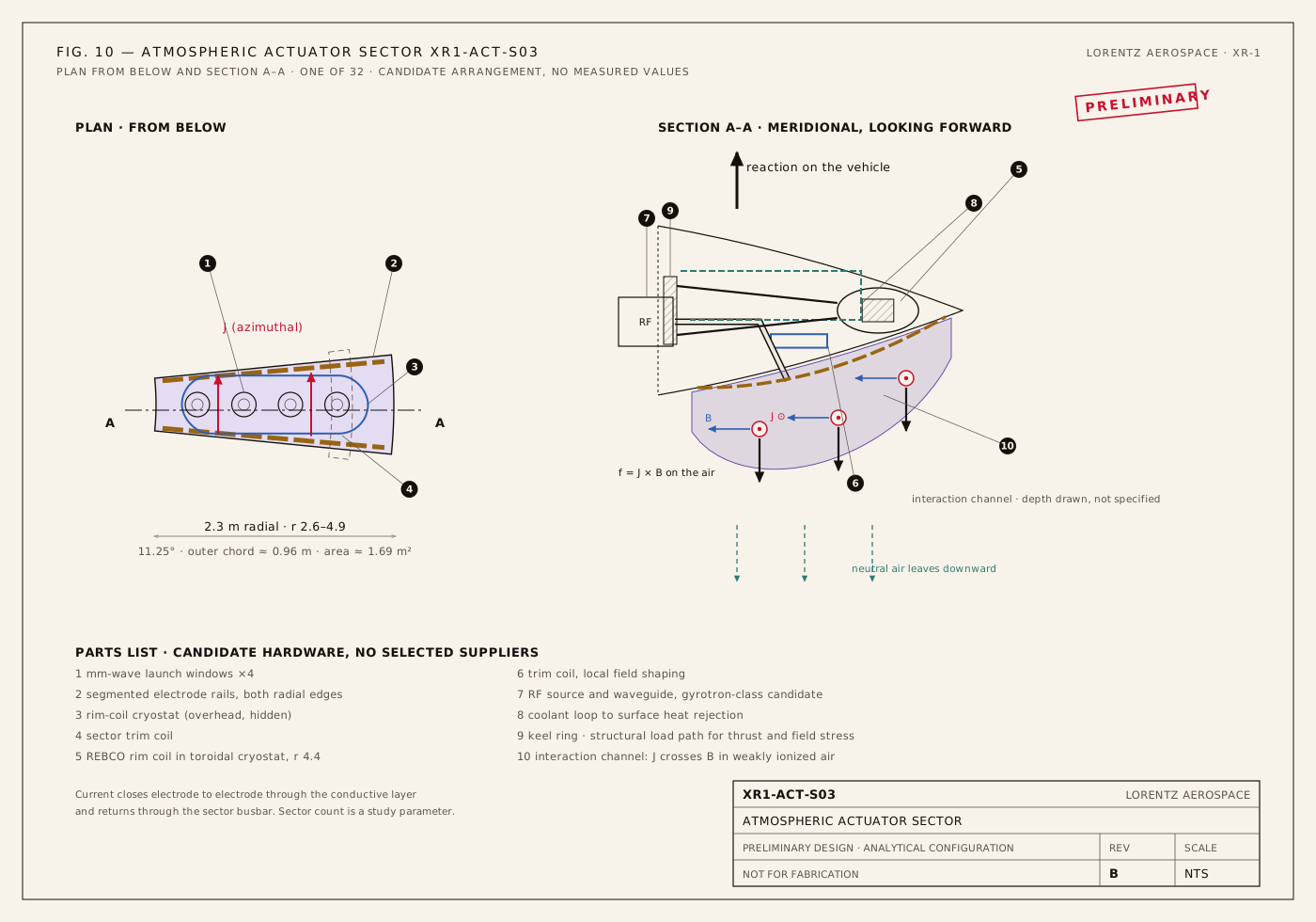
Plasma generation and current drive are separate channels. Plasma generation establishes conductivity. A slower current-drive or traveling-field system uses that conductivity to accelerate air. Changing one affects the other, but separating them makes the experiment identifiable: hold the plasma state roughly constant while varying the magnetic drive. A phased sequence of coils acts like a distributed atmospheric linear-induction drive, with phase speed $v_{\mathrm{phase}}=f\lambda$. Phase speed is not the exhaust speed. Slip, penetration, current phase and collisional transfer determine how much the neutral flow follows the field. Engineering hypothesis
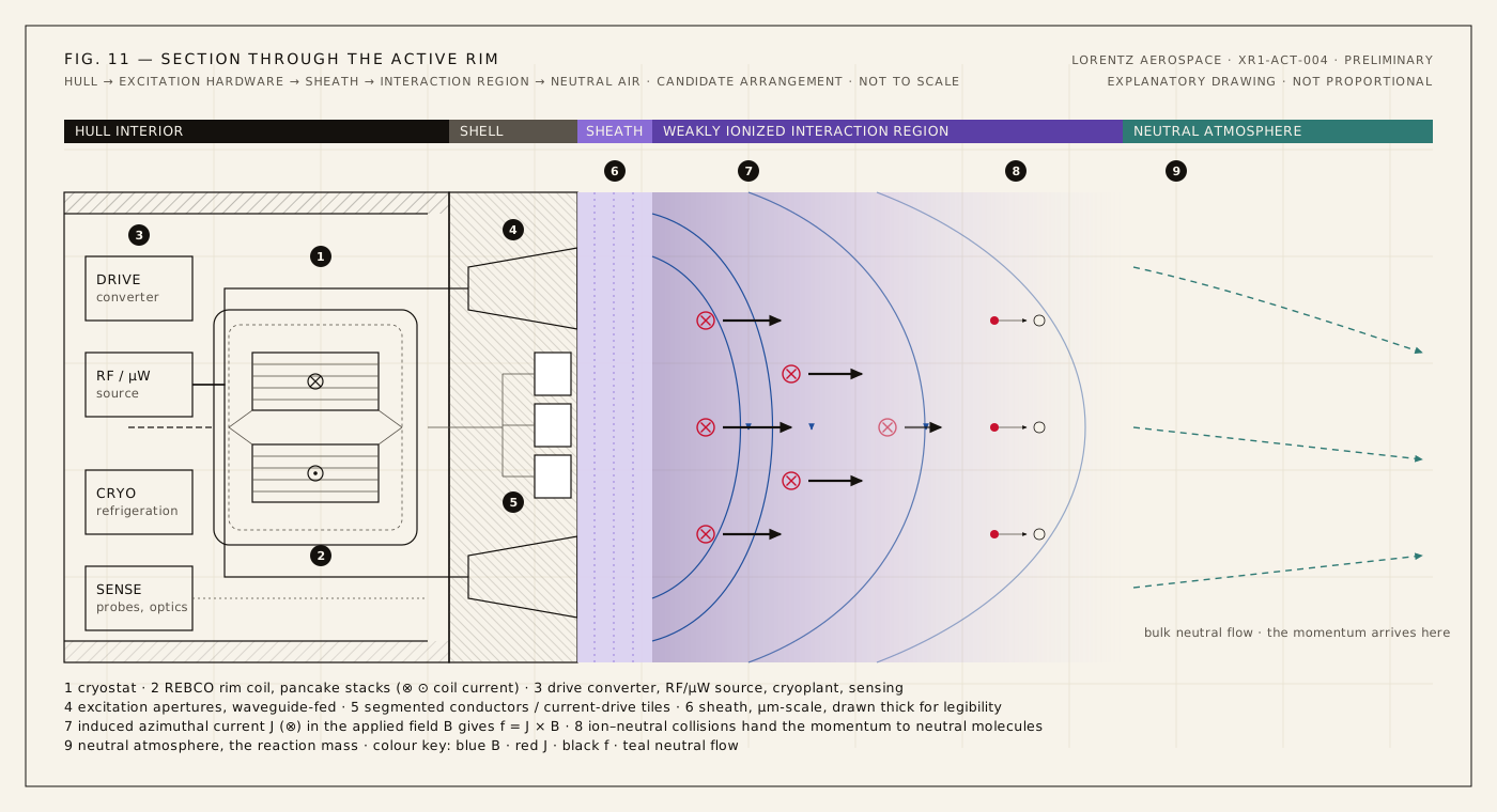
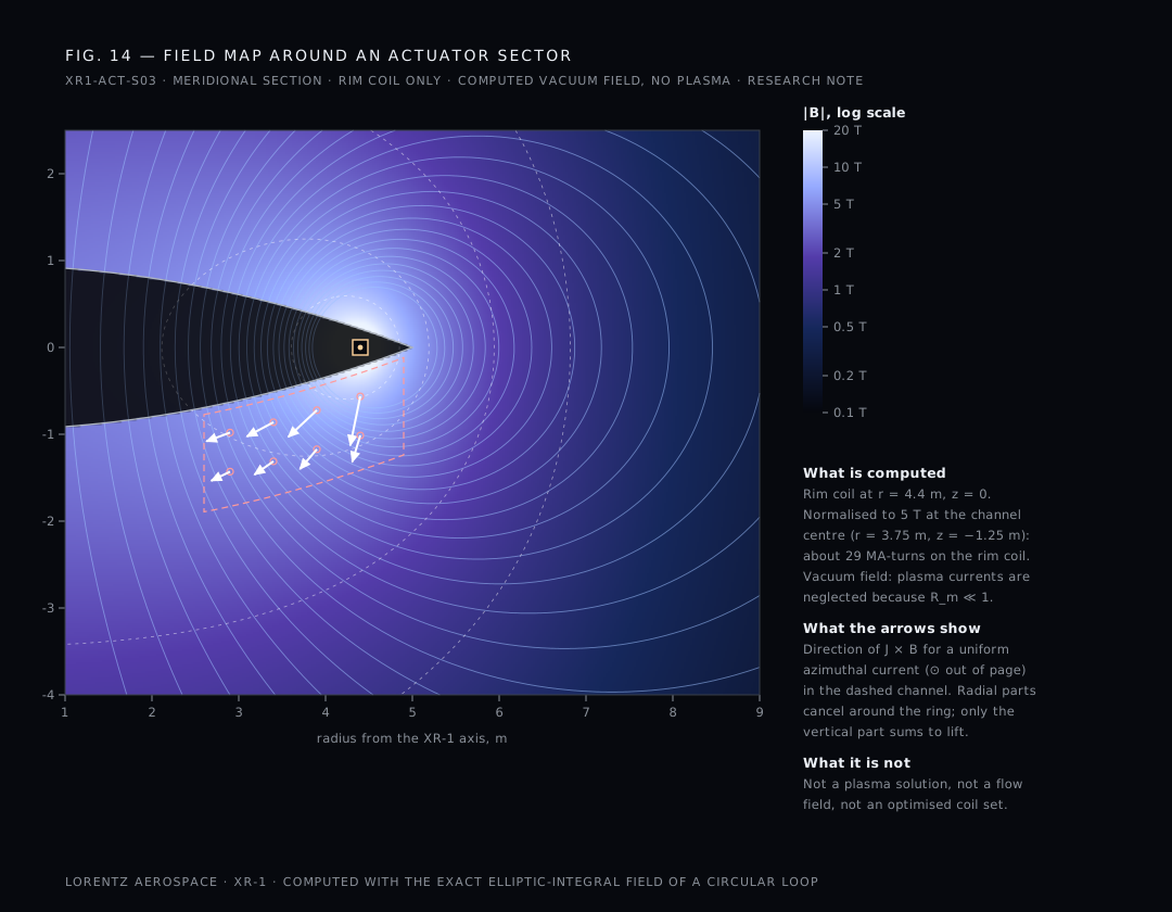
In weakly ionized air the magnetic Reynolds number is far below one. The applied field penetrates the plasma and the plasma does not carry it. That is bad news for anyone hoping to confine air magnetically and good news for anyone trying to control it: the magnetic topology is a coil-design choice, known in advance, not a plasma equilibrium to be discovered. It also means a vacuum-field calculation is a fair first map of the field the plasma will see. Established physics
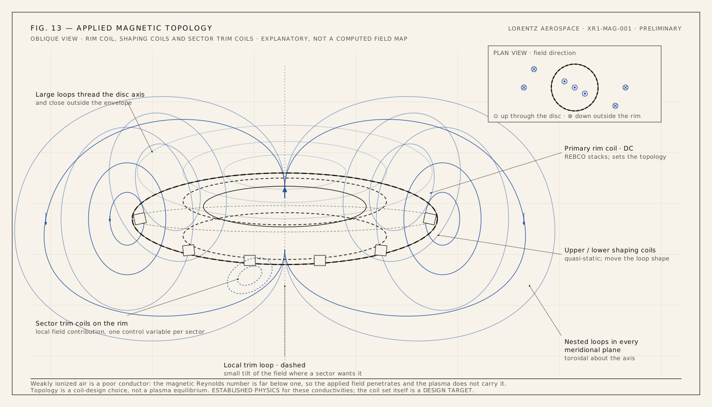
For a static field, $p_B=B^2/(2\mu_0)$ is 9.95 MPa at 5 T and 159.15 MPa at 20 T. These are local magnetic stresses on the winding and its structure. They are not available vehicle thrust, and if B is a sinusoidal peak rather than a static or RMS value, the time-average pressure carries an additional factor of one-half. Large-bore REBCO magnets have reached 20 T in a fusion test (MIT and Commonwealth Fusion Systems, September 2021); carrying such a coil set, its cryostat and its refrigeration in a flying vehicle is an open design problem. Established physics for the stress; Design target for the coil set.
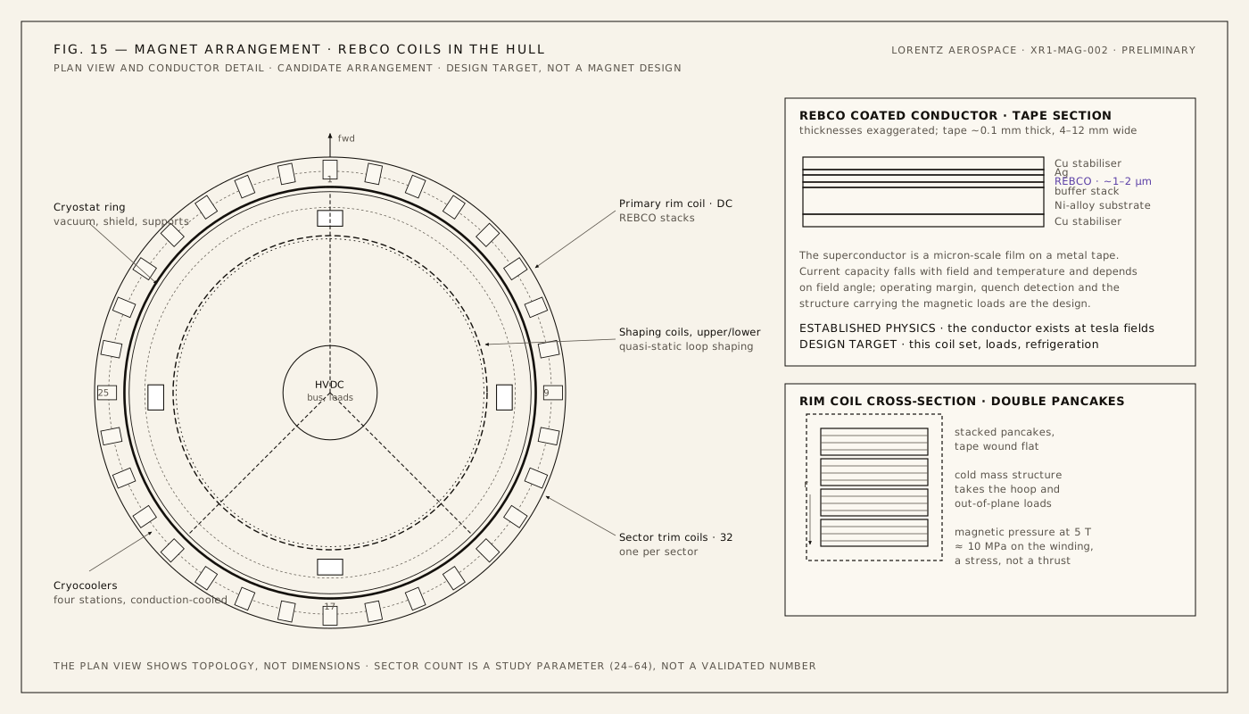
From here the page is written for plasma physicists and aerospace engineers. The introductory relation $\mathbf J=\sigma\mathbf E$ is where everyone starts, and in magnetized, collisional air it is not enough. Established physics
The electron–neutral collision frequency is $\nu_{en}=n_n\,\sigma_m\,\bar v_e$. At sea level $n_n=2.5\times10^{25}\,\mathrm{m^{-3}}$; the momentum-transfer cross section of nitrogen for electrons of a few eV is of order $10^{-19}\,\mathrm{m^2}$; the mean speed of 2 eV electrons is about $9.5\times10^{5}$ m/s. Together: $\nu_{en}\approx$ 2.37 × 10¹² s⁻¹. A collisional multifluid model therefore keeps electrons, ions and neutrals distinct rather than treating the mixture as one ideal conducting fluid, with collision rates, Hall parameters and a conductivity tensor; quasineutrality, sheath conditions and current continuity constrain charge separation and current closure. Collective plasma behavior does not establish collisionless or ideal MHD. The NRL Plasma Formulary supplies the scales. The ionization fraction at the reference density, $x=n_e/n_n$, is 4.0 × 10⁻⁸.
Pairwise exchange obeys $\mathbf R_{st}=-\mathbf R_{ts}$; reaction and injection terms must also conserve total momentum. Summed across species, internal exchanges cancel. Charged-particle force and the same momentum passed to neutral air are not two independent thrust contributions. Electrohydrodynamic ion wind also transfers neutral momentum, by a different route, and must be separated in any measurement. Established physics
Once electrons gyrate between collisions, current no longer follows the electric field. Neglecting electron pressure and ion slip, the electron momentum equation gives
or, with $\mathbf B$ along $z$, $\mathbf J=\boldsymbol{\sigma}\cdot(\mathbf E+\mathbf u\times\mathbf B)$ with a tensor conductivity
The sign of the off-diagonal terms follows the carrier charge. At 5 T and $\nu_{en}=2\times10^{12}\,\mathrm{s^{-1}}$, the electron Hall parameter is 0.440: electrons are marginally magnetized, so the Pedersen conductivity is 0.838 of $\sigma_0$ and a Hall current of 0.368 $\sigma_0$ flows across the applied field. Ions, with cyclotron frequencies near $10^7\,\mathrm{s^{-1}}$ at 5 T and collision rates of $10^9$–$10^{10}\,\mathrm{s^{-1}}$, have Hall parameters of order $10^{-3}$–$10^{-2}$: they are not magnetized at all, which is what lets them drag the neutrals. Hall currents are not free. Unless electrode segmentation or geometry lets them close usefully, they carry Joule heat and push in the wrong direction. Established physics
Two dimensionless groups decide what kind of flow this is. The Stuart number, or interaction parameter, compares the electromagnetic body force with the inertia of the flow; the magnetic Reynolds number compares field advection by the flow with field diffusion:
| Flow speed U | Case | Stuart number N |
|---|---|---|
| 5 m/s | slow inflow above the disk | 4.08 |
| 22.58 m/s | induced velocity at the disk, hover | 0.904 |
| 300 m/s | high-speed flight | 0.068 |
N increases as U decreases. At hover speeds a given conductivity and field produce a larger interaction parameter than the same hardware at flight speed; slow air is easy to push around once it conducts. The difficulty at low speed is somewhere else entirely: the gas is cold. Hypersonic MHD borrows its conductivity from the shock layer, where the air is already hot and partly ionized. At twenty metres per second nothing supplies it, and every electron must be bought with ionization power. That is the two-cost problem again, from a different direction. Established physics
The magnetic Reynolds number at hover, with the same inputs, is 2.84 × 10⁻⁵. Frozen-in-field intuition does not apply. Small $R_m$ invalidates ideal-MHD assumptions without forbidding externally driven electromagnetic force; it is the regime of electromagnetic pumps, not of stars.
Three-body attachment to oxygen, $e+\mathrm{O_2}+M\to\mathrm{O_2^-}+M$, has a rate coefficient near $2.8\times10^{-30}\,\mathrm{cm^6\,s^{-1}}$ for thermal electrons (IAEA INIS record). At sea level that gives an attachment frequency of 3.68 × 10⁸ s⁻¹, a lifetime of 2.72 ns. Heated electrons attach more slowly and detach, so the effective loss rate in a driven discharge is lower, and the $10^7\,\mathrm{s^{-1}}$ used in the two-cost table is an optimistic assumption that Gate 01 must replace with a measurement.
For $n_e=10^{18}\,\mathrm{m^{-3}}$ and 2 eV electrons the Debye length is 10.51 μm, with about 4,867 particles per Debye sphere. The electron plasma frequency $\omega_{pe}=\sqrt{n_ee^2/\epsilon_0m_e}$ is 5.641 × 10¹⁰ rad/s, or $f_{pe}=$ 8.979 GHz: in the collisionless limit, below it the layer reflects, above it the layer transmits; at sea level collisions blur that cutoff into absorption, and millimetre waves sit well above it. The fundamental electron cyclotron coefficient is 27.99249 GHz/T:
| Frequency | Matching field |
|---|---|
| 60 GHz | 2.14343 T |
| 94 GHz | 3.35804 T |
| 140 GHz | 5.00134 T |
At sea-level pressure, electron-neutral collisions can broaden or suppress resonance: the collision rate exceeds these angular frequencies, so absorption is collisional rather than resonant, and resonant heating becomes a low-pressure, high-altitude mechanism. A matching-field contour does not establish a stable closed plasma sheet. Keep three frequencies separate: cyclotron frequency depends on field, plasma frequency on density, and molecular oxygen's absorption near 60 GHz (ITU-R P.676) is a property of the molecule that heats gas rather than making plasma. Established physics
Energy reaches the air as Poynting flux, $\mathbf S=\mathbf E\times\mathbf H$. One megawatt through a 0.1 m² window is 10 MW/m², a free-space RMS field of 61.4 kV/m, far below the megavolt-per-metre fields at which sea-level air breaks down unaided. Starting the discharge therefore needs focusing, seeding or a separate initiator; sustaining it, once free electrons exist, is the part that costs power. Established physics
These are dimensional checks, not operating points. For a uniform useful volume of 50 m³ and the 98.1 kN reference load, $J=F/(BV)$ gives 392.4 A/m² at 5 T or 1,962.0 A/m² at 1 T. In a uniform, perpendicular, coherently directed interaction $F_B\approx JBV$; that is a force estimate, not an electrical power budget. Conductivity, current closure, return currents and opposing regions determine whether the useful integral can be sustained. Magnetic pressure is field stress, not available vehicle thrust.
The baseline actuator is a thin layer under the annulus. The ambition is larger. Three regimes, each harder than the last. Engineering hypothesis
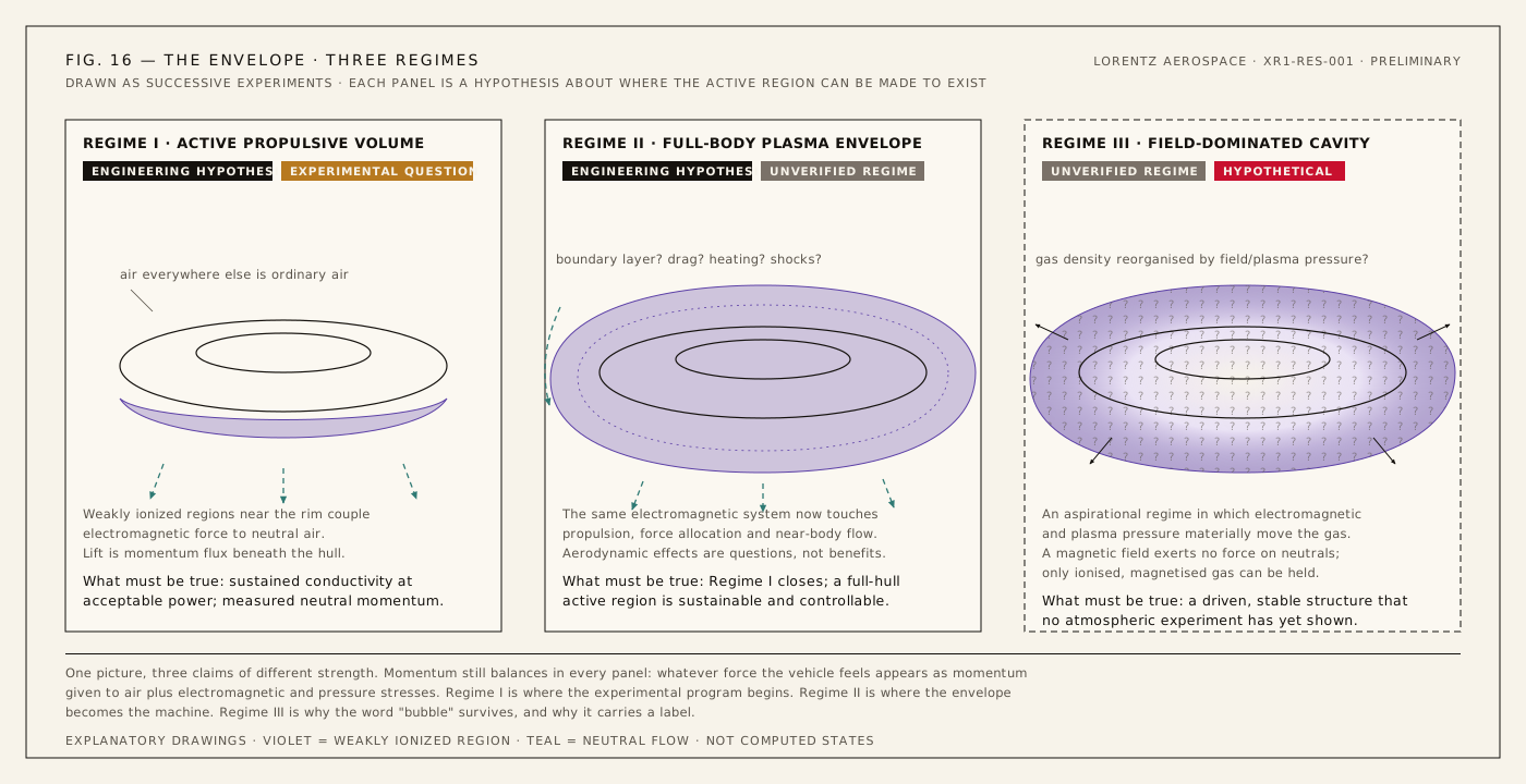
Regime I — active propulsive volume. Weakly ionized regions under the annulus couple to neutral air; everywhere else the air is ordinary. Lift is momentum flux beneath the hull; control is its distribution around the ring. This is where the program begins. Experimental question
Regime II — full-body plasma envelope. The active region grows around much of the aircraft and the same system participates in propulsion, force allocation and near-body flow. Boundary-layer behaviour, drag, heating and shock interactions become research questions, not assumed benefits. Plasma actuators have altered boundary layers at laboratory scale and magnetic fields have moved bow shocks in hypersonic test flows; neither establishes what a metre-scale envelope does to an aircraft. Simulation target Unverified regime
Regime III — field-dominated cavity. Electromagnetic and plasma pressure would reorganize the gas around the hull. Hypothetical. Requires experimental validation. The magnetic pressure $B^2/2\mu_0$ at 0.5 T is 99.47 kPa, about one atmosphere, which is why the idea is tempting. The reason it is hard is equally simple: a magnetic field exerts no force on neutral molecules, and in sea-level air the ions are collision-dominated, not magnetized. It belongs to the research horizon. Unverified regime
09
Test program
TechnicalXR-1 begins as a stationary piece of the propulsion system.
The first experiment is not an aircraft. It is one sector on a thrust stand.
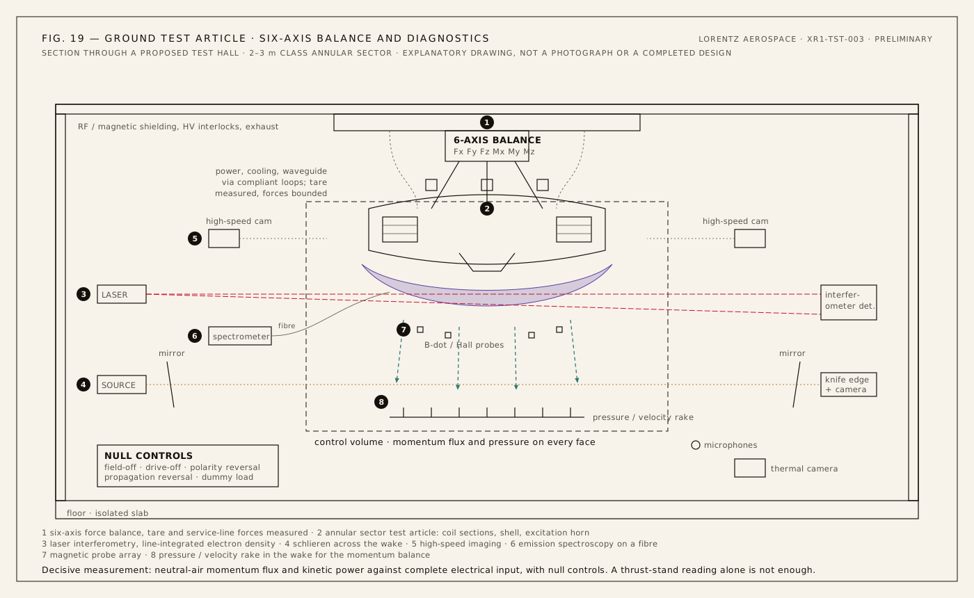
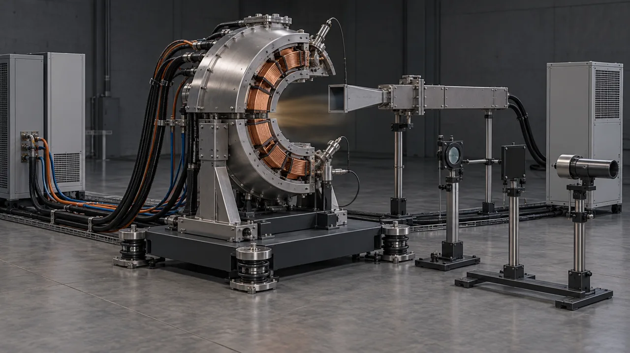
Sector S03, full scale, bolted to a six-axis balance in a qualified laboratory with high-voltage, RF, magnetic-field, cryogenic and thermal safeguards. Everything it does can be measured: the power going in, the plasma it makes, the force on the stand and the air leaving it. Progress means passing the next physical gate, not making the apparatus more elaborate. Experimental question
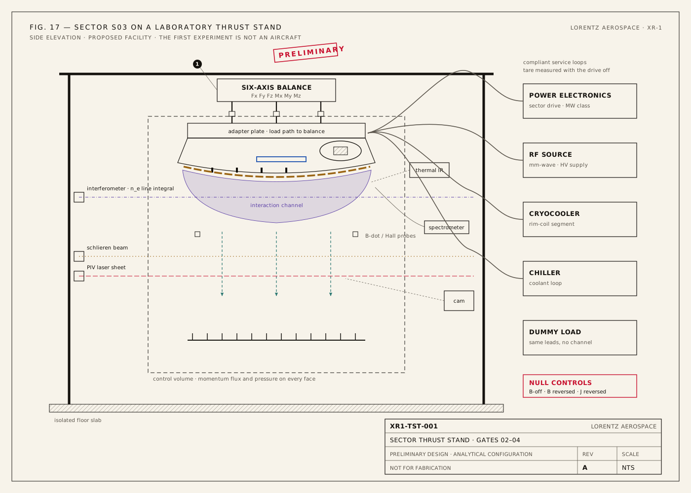
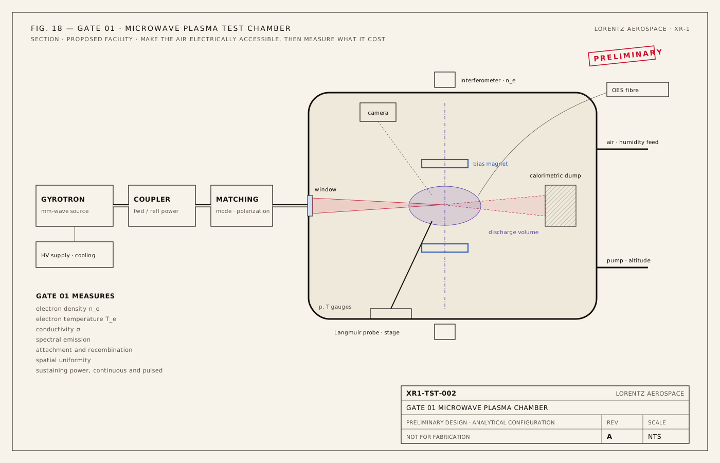
Can the required electron density and conductivity be created in atmospheric air at acceptable power?
MEASURE electron density · electron temperature · conductivity · spectral emission · attachment and recombination · spatial uniformity · sustaining power, continuous and pulsed
This gate answers the two-cost table with numbers instead of assumptions, with repeatable diagnostics and stated uncertainty.
Does energizing the magnet produce a repeatable force correlated with the predicted J × B direction?
CONTROLS B-off · field reversal · current reversal · dummy loads · cable-force controls · thermal controls
Explicitly separate magnetic thrust from EHD, thermal buoyancy, vibration, cable forces, corona wind and measurement artifacts. B-off and reversal controls distinguish ion wind and thermal effects from the intended magnetic contribution; bound cable, ground, nearby-structure and pressure forces. A single thrust-stand reading is not enough. Glowing plasma does not prove thrust. Plasma luminosity is not evidence of useful coupling.
Is electromagnetic force becoming bulk neutral momentum?
MEASURE PIV and schlieren · wake velocity · mass flow · pressure field · momentum flux · temperature
Map the neutral momentum flux over a closed control volume and compare it with the force on the balance. No mechanism is validated merely by naming the flow.
How much electrical input becomes directed atmospheric kinetic power? This is probably the single most important number in the program.
MEASURE directed-air kinetic power · every electrical input · effective area and loading · heat and other losses, with uncertainty
Newtons per kilowatt is area- and loading-dependent; numerical efficiency bands are screening scenarios, not universal viable/dead thresholds. Repeat across operating conditions and seek independent reproduction.
Can multiple sectors produce controlled vector thrust?
TEST differential sector power · pitch · roll · yaw · vertical force · lateral translation · dynamic stability
Include actuator limits, transients, saturation, failed sectors and safe loss of power on a constrained rig. This is the gate at which the allocation diagram in section 11 becomes either a control law or a drawing.
The denominator includes RF source wall-plug power, bias and current drive, field-drive losses, cryogenics, cooling, sensing, control and auxiliaries. The numerator is the measured directed neutral-air kinetic-energy flux: subtract the inlet baseline and account for pressure work, swirl and recirculation. The XR-1 reference point needs at least 22%.
Useful thrust is not the first gate. Useful thrust per electrical watt is.
| Item | Scope | Status |
|---|---|---|
| XR1-GA-001 | General arrangement, reference geometry | REV B · PRELIMINARY |
| XR1-ACT-S03 | Actuator sector drawing | REV B · PRELIMINARY |
| XR1-TST-001 / 002 | Thrust stand and Gate 01 chamber architecture | ARCHITECTURE |
| Gate 01 · Plasma | Conductivity and sustaining power | OPEN · NOT STARTED |
| Gate 02 · Force | Repeatable J × B force with null controls | OPEN · NOT STARTED |
| Gate 03 · Neutral coupling | Wake momentum flux against balance force | OPEN · NOT STARTED |
| Gate 04 · Efficiency | ηatm with uncertainty | OPEN · NOT STARTED |
| Gate 05 · Control | Multi-sector vector thrust | OPEN · NOT STARTED |
Only after these gates close does the aircraft become the experiment.
Then tethered lift, then an aircraft whose power, mass, cooling and reserves close together. The decisive result throughout is measured neutral-air momentum and kinetic power against complete electrical input. If it is useful and reproducible, it earns the next engineering step. If it is not, this page will say so.
10
Power
TechnicalThe power architecture is jet fuel → turboshaft → generator → DC bus → actuator sectors. Nothing exotic, and nothing small. Design target
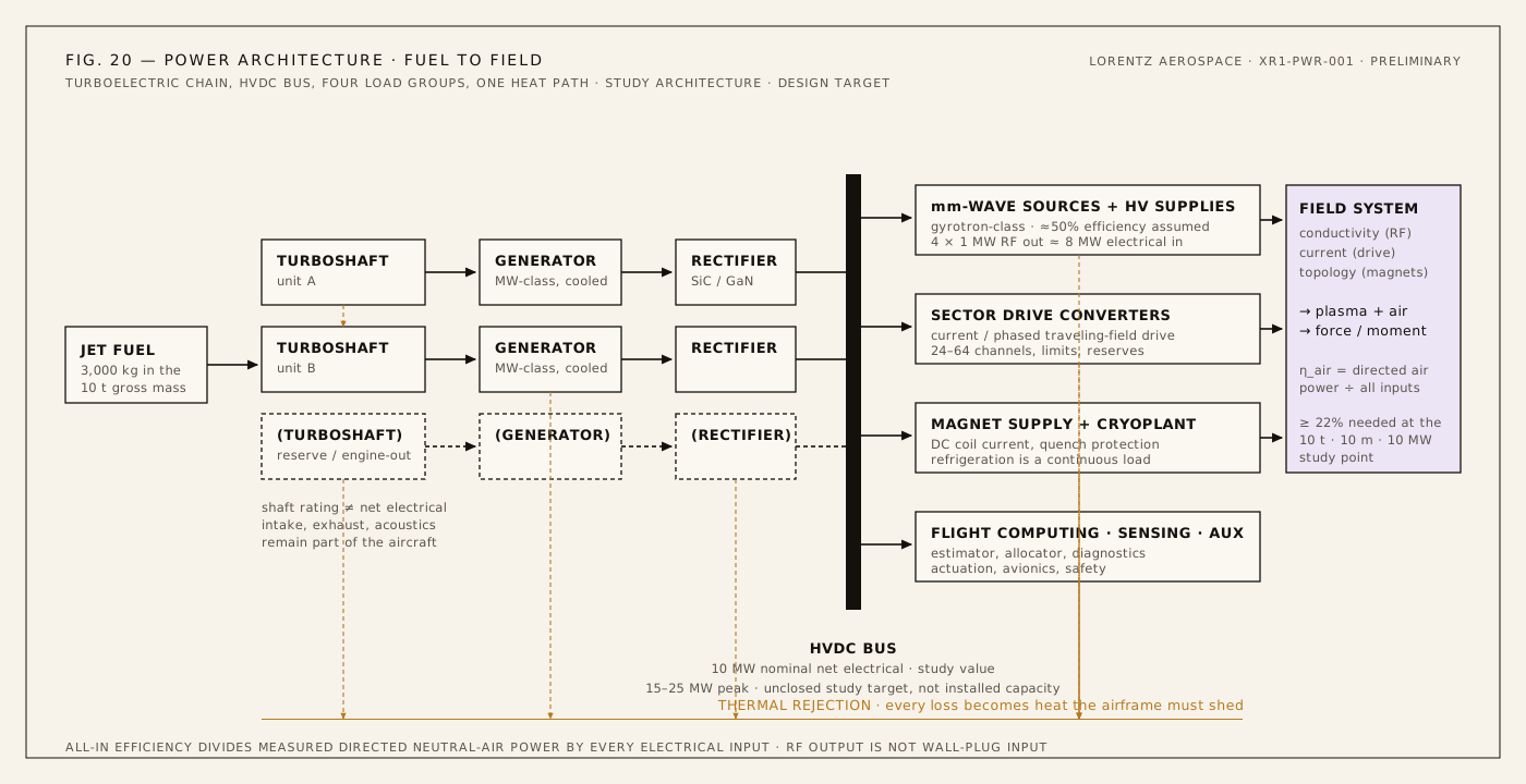
| Gross mass, including fuel and every subsystem | The specified gross mass includes the complete aircraft. |
|---|---|
| Assumed effective actuator diameter | The study interaction scale; the momentum table defines area, load and ideal airflow power. |
| Net electrical input to the complete actuator system | The nominal input covers every load within the boundary. |
| Fuel carried inside gross mass | 3,000 kg |
| Remaining allowance for hardware, structure and payload | 7,000 kg; not a demonstrated mass closure |
| Assumed fuel LHV / net fuel-to-electric efficiency | 43 MJ/kg / 30% |
| Fuel flow at the stated electrical load | 0.7752 kg/s = 2.791 tonnes/hour |
| Electrical energy from the fuel allowance | 38.7 GJ |
| Constant-load energy duration | 64.5 minutes, before reserves or mission effects |
This is a linked energy scenario, not a mass-closed aircraft endurance claim. The 43 MJ/kg fuel assumption is representative of jet-fuel values in a NASA aviation-fuels report; 30% net conversion is an explicit study assumption. Engine part-load behaviour, changing weight, reserves and a real mission need their own analysis.
An hour of hover burns almost three tonnes of fuel.
That is the honest shape of the machine: about 33 MW of fuel power flowing through the airframe to deliver 10 MW to the bus and, at the reference point, at least 2.2 MW to the air. It is a heat engine with an electromagnetic output stage. The numbers make XR-1 an engineering study rather than a free lunch, and they point at where the leverage is. Design target
For the same 10 t / 10 m point, 15–30% all-in efficiency implies 7.383–14.767 MW of electrical input. Across 10–12 t and 10–20 m effective diameters, ideal power spans 1.1075–2.9117 MW; combining that range with 15–30% gives 3.692–19.411 MW. The same power budget cannot cover every geometry and efficiency combination.
11
Control without surfaces
TechnicalIf the sectors can be driven independently, the distribution of force around the ring becomes the control surface. Segmented thrust vectoring is a research objective of the program, not a demonstrated capability; Gate 05 decides it. Engineering hypothesis
Each sector could vary its RF excitation power, local conductivity, current amplitude and phase, traveling-field phase, trim-coil field, duty cycle and pulse timing. Not every variable can be commanded arbitrarily or instantaneously: the sectors share power, share the magnetic topology and interact through the gas between them. Design target
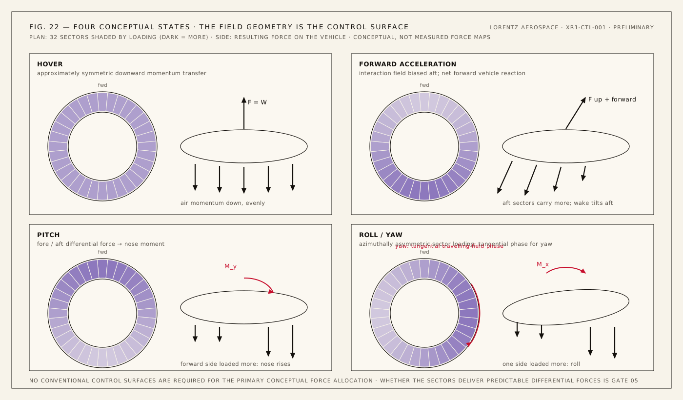
The pilot commands vehicle motion. A hierarchy of control systems translates desired forces and moments into a spatial electromagnetic interaction pattern, in the spirit of fly-by-wire, except that the actuator is a distributed plasma and field system. Inner loops regulate measured current and inferred plasma state; a constrained sector allocator distributes commanded forces and moments; an outer loop closes on vehicle motion. Allocation must include moment balance, saturation, reserves and failed sectors. Design target

The controller must continuously estimate an unobservable high-dimensional plasma state from incomplete sensors, then choose the sector commands whose predicted effect best matches the demand within every limit. Interferometry, emission spectra, probes, electrical measurements, pressure and airflow sensors give calibration- and model-dependent state estimates; inertial units measure vehicle motion. Offline coupled plasma-chemistry, electromagnetic and gas-flow models inform reduced-order onboard estimators, which must be shown to track the full models before they are trusted in a loop. The same class of problem, on a very different plasma, was solved on a tokamak with a learned controller in 2022 (Degrave et al.). The transfer is of method, not of result. Simulation target
The propulsion problem is inseparable from the computation problem.
RF carrier or switching frequency is not feedback bandwidth. Sensor latency, gas response, stability margins, thermal and current limits, magnet quench and safe loss of power set the achievable rates. Modern control cannot rescue poor coupling. Established physics
12
Falsification
The architecture makes claims that can fail. These are the ways it fails.
These are experiments, not philosophical questions.
A research organization follows the measurements. These results would move it, in either direction.
Each gate on the test program maps to one or more of these lines. A negative result is a result; it will be reported here as prominently as a positive one. Experimental question
13
Lineage
People could conceive of pieces of this machine decades ago. They could not control, power or simulate it. What follows is documented work by other people and other institutions: the technical ancestry of the problem, not an institutional lineage. Lorentz Aerospace inherits none of it, claims none of it, and implies no endorsement by any of it.
Every entry is a published result by named people; the links go to the sources. The implication is ours: the conductors, the sources, the diagnostics, the converters and the computation each arrived separately, mostly for fusion and space, and only recently did all of them exist at once at the scale the problem needs. Engineering hypothesis
14
Research horizon
ResearchBeyond the XR-1 baseline lie questions with their own proof requirements. None of them is needed to test the propulsion hypothesis, and none supplies a missing result for it. They are where the program goes if the gates close. Unverified regime
XR-1 does not require fusion to test the propulsion hypothesis.
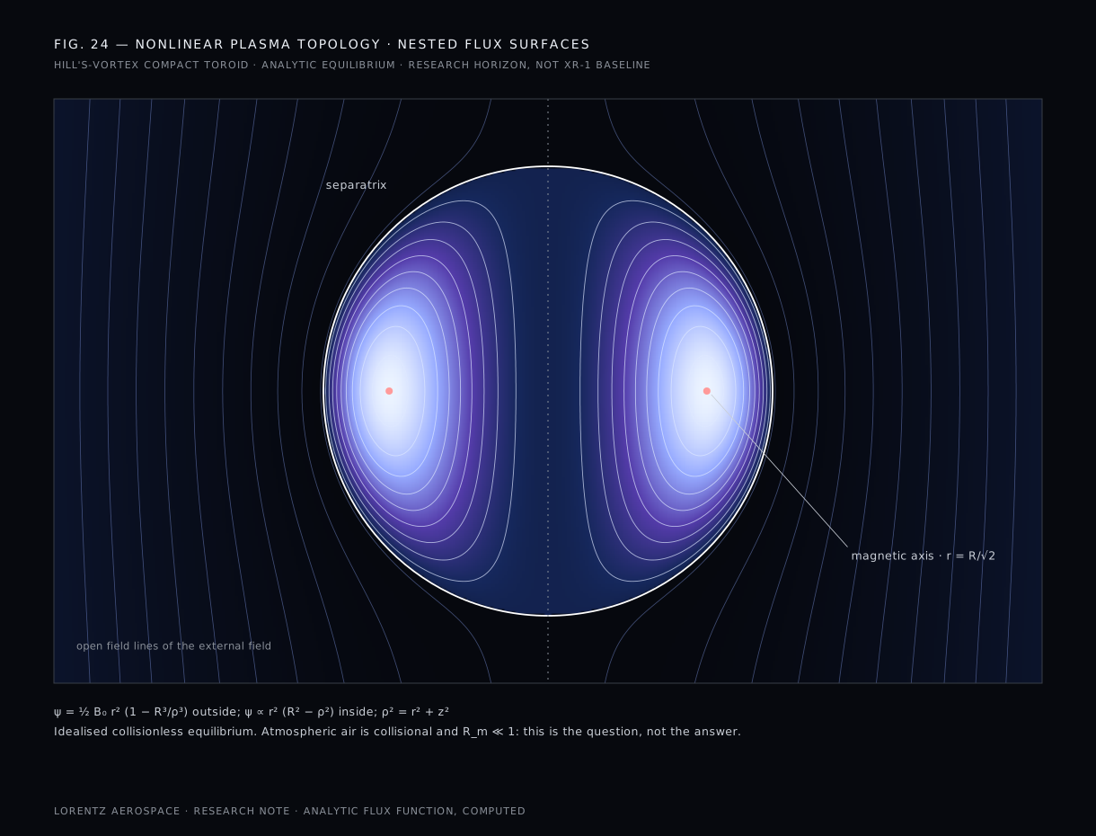
Can driven nonlinear configurations create more stable interaction volumes? A self-organised structure, a compact toroid or a three-dimensional soliton, would be a way to hold a large conducting region together with less continuous forcing. A one-dimensional mathematical solution does not prove stability of a closed, driven, dissipative surface, and a magnetically maintained cavity (Regime III) would need a stable three-dimensional boundary, gas exclusion and pressure balance in collisional air. Begin with measured local stability and transport before assigning either a vehicle function.
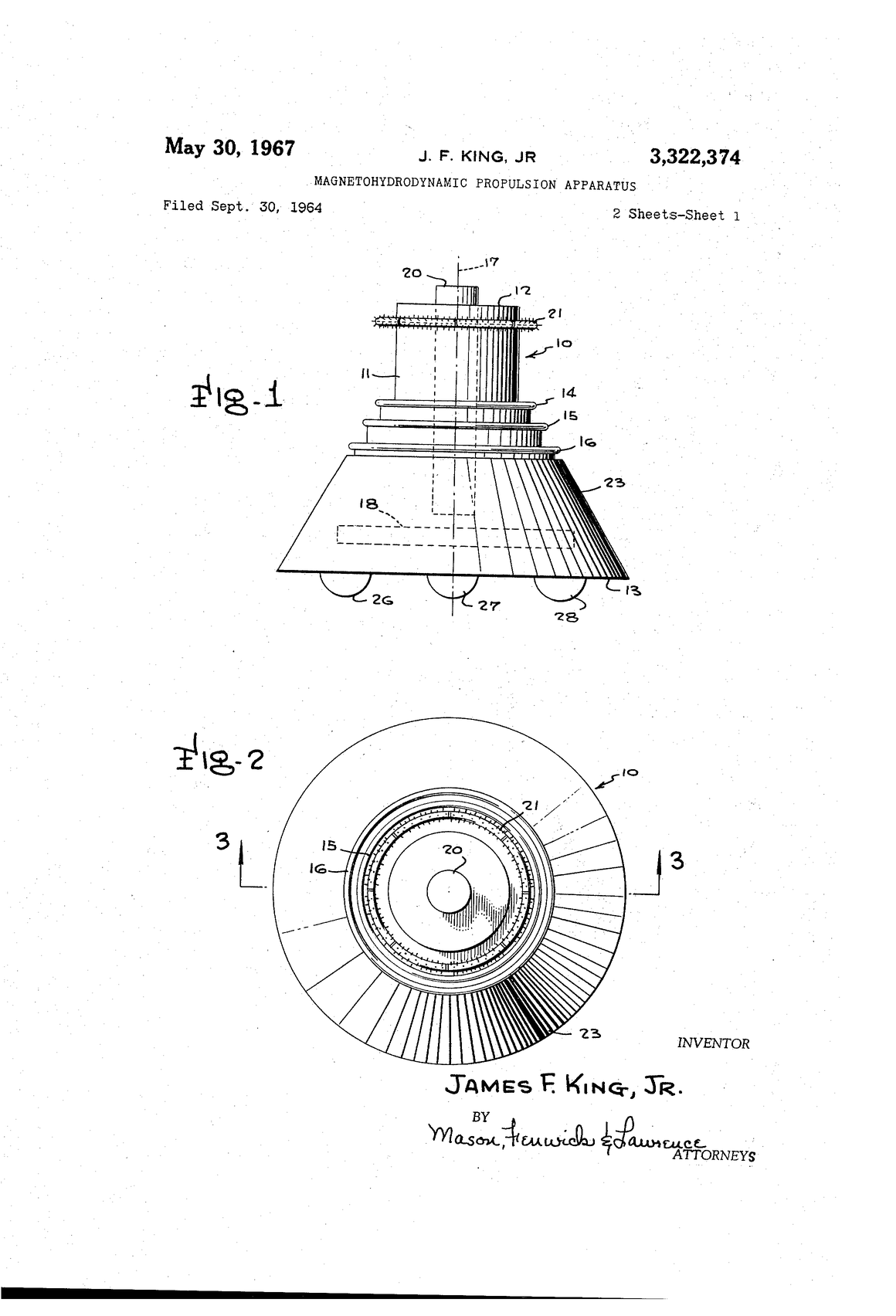
Can traveling or rotating fields give better current closure and momentum coupling than static electrodes? An induced azimuthal current needs no electrode at all; it closes on itself around the ring, as in King's patent and in every linear-induction machine. Slip, penetration depth and the low magnetic Reynolds number decide how much of the field's momentum the air accepts.
Can high-frequency fields manipulate conductivity or boundary conditions with lower bulk heating? Terahertz excitation is a candidate surface and sheath research topic. Frequency alone does not establish micron-scale control resolution, useful force authority or propulsion efficiency.
Bi–Mg structures and engineered metamaterials are candidate topics for the plasma-facing surface and sheath, only where they are technically defensible. Composition alone does not establish a useful electromagnetic response; characterization must determine dispersion, absorption, heating, durability and coupling to the actual plasma boundary. No material on this page has mysterious properties.
Compact fusion or other advanced sources could radically alter endurance. They are separate experimental programs, not available XR-1 sources. Any integration would require both the reactor and the atmospheric actuator to demonstrate useful complete-system performance independently, then a joint mass, shielding, cooling and safety budget. The turbogenerator reference case depends on none of it.
15
Archive
Research libraryThe research library behind the program: technical reports, prior art, calculations and simulation notes. Each entry is closed by default.
Dimensional checks, not operating points. Electron–neutral collision frequency $\nu_{en}=n_n\sigma_m\bar v_e$ with $\sigma_m\sim10^{-19}\,\mathrm{m^2}$; scalar conductivity $\sigma_0=n_ee^2/m_e\nu_{en}$; Hall parameter $\beta_e=\omega_{ce}/\nu_{en}$; plasma frequency $\omega_{pe}=\sqrt{n_ee^2/\epsilon_0m_e}$; Debye length $\lambda_D=\sqrt{\epsilon_0T_e/n_ee^2}$. Values at $n_e=10^{18}\,\mathrm{m^{-3}}$, 2 eV and 5 T are quoted in section 08. A scalar approximation gives $R_m=\mu_0\sigma UL$; small magnetic Reynolds number invalidates frozen-in-field assumptions without forbidding externally driven force. The energy per ion pair in air, 33.97 eV, is the recommended dosimetry value and a floor for a discharge, whose cost per electron is usually higher.
| Function | Candidate role | Evidence that selects it |
|---|---|---|
| Magnetic topology | DC or quasi-static bias | Field map, transport anisotropy, stress and cryogenic limits |
| Electron heating | RF/microwave; GHz source candidates | Breakdown, absorption, conductivity and sustaining power |
| Collective organization | Lower-RF perturbations, potentially MHz | Measured modes, damping and penetration |
| Momentum drive | Lower-frequency phased/current-drive sectors | Slip, current phase, neutral-air momentum and losses |
| Feedback | Nested loops with measured response times | Sensor delay, stability margins and safe limits |
Studies using 64–256 sectors or MHz/kHz/100 Hz hierarchies use assumed parameters, not validated sector counts or feedback bandwidths. Carrier, switching, plasma relaxation and controller update frequencies are different quantities. Converter device selection among IGBT, SiC and GaN depends on voltage, current, switching loss and cooling at the rating.
Why ideal magnetohydrodynamics does not describe sea-level air: collisions outpace the plasma frequency about 35 times, $R_m\sim10^{-5}$ leaves the coils' vacuum field in place, and Alfvén disturbances diffuse before they propagate. The low-$R_m$, multi-species working set that replaces it, and why magnetic pressure loads the windings rather than the air. Full report.
King's magnetohydrodynamic propulsion apparatus, US 3,322,374, describes atmospheric ionization and sequential magnetic excitation: a corona ionizer ring, polyphase superconducting driving rings producing a traveling field, and segmented ionizer sectors for steering. It is conceptual prior art for separating a conductive working medium from the traveling-field drive, not evidence that the aircraft achieved useful performance. The patent expired decades ago; the physics it describes is public. Full prior-art note.
Research on magnetic plasma control supplies tools rather than flight validation. Magnetic control on the TCV tokamak concerns a measured fusion-device plant. Electrohydrodynamic flight (Xu et al., 2018), dielectric-barrier-discharge flow control (Corke, Enloe and Wilkinson, 2010) and seawater MHD propulsion (Yamato-1) are measured neighbours of this problem, not answers to it.
The literature the program reads, by subject: plasma physics, magnetohydrodynamics and magneto-aerodynamics, gas discharges and air chemistry, electric propulsion, momentum theory, magnets and sources, plasma control and simulation, and background for the research horizon. Full bibliography.
$T=mg=98.1$ kN; $A=\pi(5\,\mathrm m)^2=78.54\,\mathrm{m^2}$; $v_i=\sqrt{T/2\rho A}=22.58$ m/s; $\dot m=\rho Av_i=2{,}172$ kg/s; far wake $2v_i=45.16$ m/s; $P=Tv_i=2.215$ MW. Annulus only ($r=2.6$–$4.9$ m, $54.19\,\mathrm{m^2}$): 2.667 MW. Minimum ideal-power / input ratio at 10 MW: 22.15%.
Ohmic: $P_\Omega\approx F^2/\sigma B^2V$ = 7.70 MW at σ = 1 S/m, B = 5 T, V = 50 m³. Sustaining: $n_e\nu_{\mathrm{loss}}W_i$ = 54.5 MW/m³ at $10^{18}\,\mathrm{m^{-3}}$, $10^7\,\mathrm{s^{-1}}$, 34 eV. Endurance: 3,000 kg × 43 MJ/kg × 30% = 38.7 GJ; at 10 MW, 64.5 minutes; fuel flow 0.7752 kg/s.
These operator-supplied illustrative allowances are not supplier quotations, current market prices, a validated program estimate or a procurement plan. Exclusions, contingency, development risk and possible overlaps are unpriced. The stationary coupling experiment remains the first gate.
| Subsystem | Low | High |
|---|---|---|
| Turbogenerators | 8 | 15 |
| HTS magnets | 15 | 40 |
| Magnet structure, cryostat, quench | 8 | 20 |
| Gyrotrons | 5 | 12 |
| Gyrotron HV, cooling, transmission | 4 | 10 |
| Plasma initiators | 2 | 5 |
| Propulsion coils | 5 | 12 |
| Power electronics | 8 | 15 |
| Cryogenic plant | 3 | 8 |
| Thermal management | 3 | 7 |
| HVDC bus | 3 | 6 |
| Plasma diagnostics | 2 | 5 |
| Flight sensors | 1 | 3 |
| Computing and control | 2 | 5 |
| Airframe | 5 | 15 |
| Fuel system | 1 | 3 |
| EMI protection | 2 | 6 |
| Integration and testing | 20 | 50 |
| Arithmetic subtotal | 97 | 237 |
Before hardware, the coupled plasma-chemistry, electromagnetic and gas-flow models must reproduce a measured discharge: electron density and temperature, both costs of the two-cost table, and the wake of a single sector. Only then are their predictions for a vehicle believed. Model output is not evidence. Simulation target
Fig. 14 uses the exact field of a circular current loop in complete elliptic integrals, evaluated on a meridional grid, with field lines drawn as contours of the flux function $\psi=rA_\phi$. The vacuum approximation holds because $R_m\ll1$ in weakly ionized air. The force arrows assume a uniform azimuthal current density in the channel; a real channel will have Hall currents and nonuniform conductivity.
Machine-learning and reduced-order surrogates may stand in for slow physics inside the loop, validated against the full models and against measured discharges. Each application needs its own diagnostics, dynamics and stability margins.
A lattice-Boltzmann flow solver driven by a computed $\mathbf J\times\mathbf B$ body force, with heat and buoyancy, to predict the wake of one sector on the thrust stand before Gate 03 measures it. Validated step by step against the gates, never ahead of them. Full note.
16
The atmosphere is already there.
The question is whether electricity can become the rotor.